Tollbooth project
Explanation
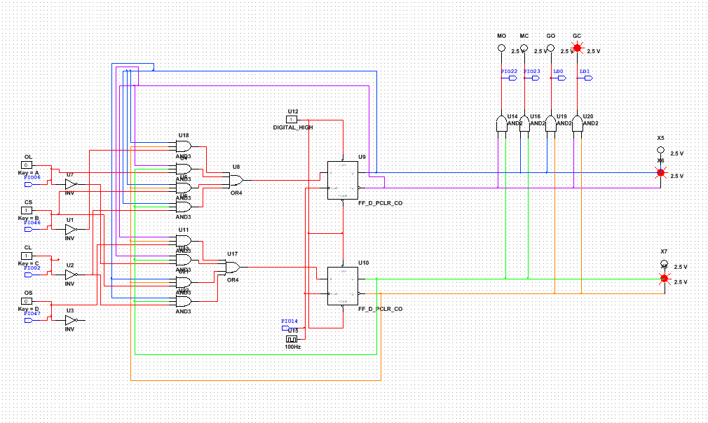
This project required 4 inputs, 4 outputs, and 4 states. The inputs were Open Limit (OL), Close Limit (CL), Open Switch (OS) and Close Switch (CS). The outputs were Motor Open (MO), Motor Close (MC), Gate Open (GO), and Gate Close (GC). State 0 occurs when the gate is closed, so CL is 1, which means that GC is one as well. To move on to the State 1, OS has to be pressed externally, so OS has to equal 1, which causes MO to equal 1. When the gate opens all the way, it presses OL, which moves the gate to State 2, which means that GO equals 1. And finally when CS is pressed externally and equals 1, the gate closes (State 3) and MO equals 1.
This entire procedure causes the gate to open and close accordingly- open when the OS is pressed and close when the CS is pressed.
The procedure is based on the present states which are determined by Qa and Qb.
This entire procedure causes the gate to open and close accordingly- open when the OS is pressed and close when the CS is pressed.
The procedure is based on the present states which are determined by Qa and Qb.
Multisim
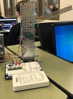
vex
Conclusion
We used the packet as an outline for our design process. The first thing we did was build the Vex tollbooth based on the photos in the packet. This was straight forward and very easy. Then we began working on the state graph and transition table. This was more difficult because we were a little confused by all of the inputs and outputs. However once we figured it out, we were able to complete the state graph, transition table, and simplified logic expressions. Based on those expressions we made the Multisim, which was pretty easy. Then we had to use the schematic and pictures to breadboard the cmod chip and other circuit components. This was the hardest part because the schematic and pictures were difficult to read. This project was similar because we used the cmod chip and multisim, however it was different because of the extra breadboarding we had to do, and the conjunction of multisim and vex equipment to make the project work. We also had to do our first state graph and transition table completely on our own in this project. I learned that reading schematics isn't that difficult as long as you understand the components in your project and how each of them functions, and it was easier than in the beginning of the year because I understood how to read them, however it was also harder because the components in the projects were more complex. The only thing I would do differently next time is check to see if the clock is running before we test the program, so that we dont waste time trying to fix other things that work!
