60 second timer
project overview

In this project we designed a circuit that counts from 0-59, with a reset button. The 10s place used J/K flip flops and the ones place used a 74LS163 counter.
PLD circuit

This project is similar to the DMV project in that the 10s place is clocked by the 1s place and that there is a reset switch. However the DMV project used a 74LS93 in the 1s place and D flip flops in the 10s place. In 60 second, the 1s place uses a 74LS163 and the the 10s place uses J/K flip flops. Also the DMV project used a suspend count count system so once the count reached 80, the count would stop until a switch was toggled. In the 60 second project the count automatically reset to 0 and continued counting once the count reached 59. The switch was used to reset the clock back to 0.
conclusions
Synchronous circuits are each clocked simultaneously by the same external clock, while asynchronous circuits have one segment clocked by an external clock, while the remaining segments are each clocked by the output of the previous segment. This creates a ripple effect. A '193 is a 4-Bit up and down counter with a preloadable count start and an asynchronous load and clear. The '193 must detect the number after the desired output to clear. The '163 is a 4-Bit up counter with a preloadable count start and a synchronous load and clear. The '163 detects the desired number in order to clear.
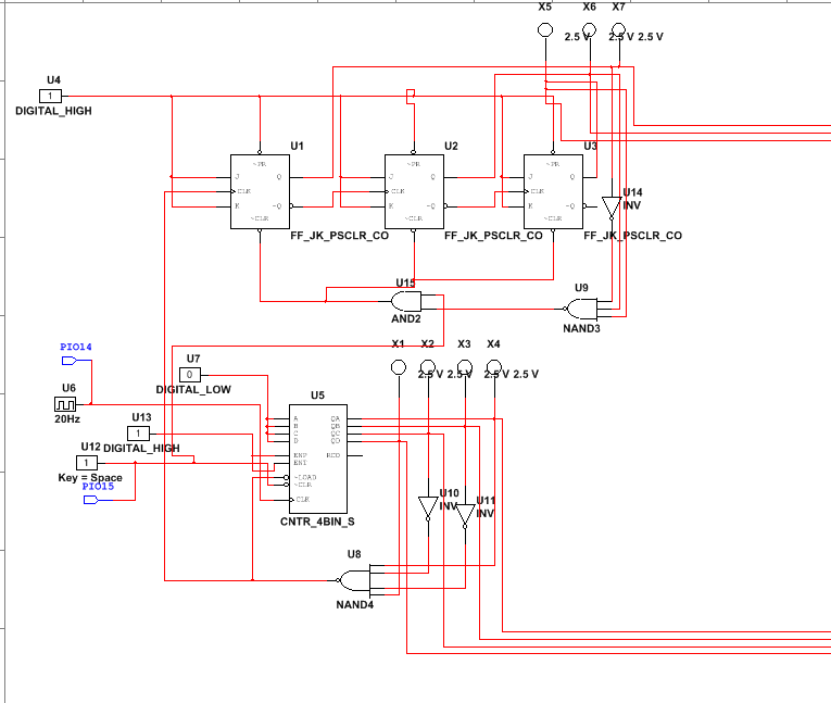
To start this project I began by working on the 74LS163 for the ones unit display. Because this needed to count from 0-9, the inputs each had to be grounded, and the outputs were wired so the 4-input NAND gate would detect a 9. This was then connected to the LOAD, while the END and ENT were powered, the CLK was connected to a clock, and the CLR was connected to a switch. Then I began working on the tens place J/K flip flops. Each of the J/K inputs and the Preset inputs were attached to power. Since this was supposed to count to 5, the outputs of each flip flop were arranged so that the NAND gate that they were connected to read a 6. This output was then connected to an AND gate that also had an input from the switch by the ‘163. The AND output was then connected to the clear of each flip flop. The output from the NAND gate of the ‘163 then connects to the Clock of the asynchronous J/K flip flops so that the tens place is clocked by the ones place. Also for the tens place to count up, the clock of each segment except for the first had to be connected to the NOT Q of the previous flip flop, since the clock and NOT Q are opposites. Then, the outputs of the J/K flip flop and the 74LS163 had to be connected to the 74LS48s found in Mrs. Z’s downloadble circuit. From there were assigned to the clock and switch, and the board was wired accordingly. Finally, the circuit was transferred to the CMOD chip.
Most circuit designs in the class were very similar, however when there were differences, it was mostly just in the implementation of the reset button, where they used more or less NAND or AND gates.
