Copy Jam project
The goal of this project was to create a circuit that alerted a copy machine user of a copier malfunction or jam. To do this, a phototransistor detected when two adjacent light streams emmitted by LEDs at 3 different checkpoints were broken. Under normal working conditions, this would not happen, however, during a jam, adjacent light streams would be broken. When the phototransistor detects this, a separate LED turns on, and a buzzer sounds. The LED turns off as soon as the jam is fixed, however a reset button is required to turn off the buzzer.


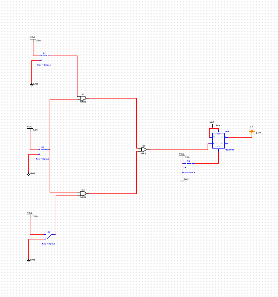
This circuit used 3 switches, a D flip flop, 2 AND gates, and an OR gate.
We also had to use resistors when breadboarding because they allowed the power to cycle through the circuit continously if no jam is detected. The combinational logic circuit allows multiple inputs to provide feedback, that under certain circumstances, will initiate a response. The flip flop allows the buzzer to sound until it is reset because of its Clear component. The LED turns off when the jam is fixed however, because it is not connected to the flip flop and directly represents the state of the copier.
This project is different than others we have worked on because instead of just creating the circuit component of a project as we have done in the past, we also built the "machine" itself that our circuits responded to. This project also had us respond to a real life situation, whereas other projects simply had us respond to a prompt. This project taught me that it is very difficult to connect both a "machine" and a circuit. I also learned that sometime two heads aren't necessarily better than one, because even though the whole class tried to complete this project together, we still struggled. A lot. And finally, I learned that perserverance is key, because that is the only way that progress is made.
